The Mastery Of Electrical Systems in Cars

The electrical system is one of the most important yet complex systems in modern vehicles. It provides power to run all the electrical accessories and electronics, controls the engine and transmission, charges and protects the battery, and gives signals to indicate proper operation or warnings when something goes wrong.
Understanding the fundamentals of how electricity flows through the various circuits in a car and being able to diagnose and fix electrical issues is essential for anyone who wants to fully master automotive repair and maintenance. This detailed guide will provide a comprehensive overview of electrical systems to build expertise.
Table of Contents
Electrical Basics
Electricity involves the flow of electrons through a conductive path. Certain metals like copper have free electrons that can move easily. The flow of these electrons is the electric current. Voltage is the electrical potential that causes electrons to flow to complete the circuit. Power is measured in watts, and is the product of voltage and current.
Resistance opposes and limits the flow of electric current. Insulators like plastic have very high resistance. Conductors like metal have low resistance. Parallel paths provide less total resistance. Extended length or smaller wires increase resistance. Connections also contribute resistance.
Electricity takes all parallel paths back to the source. Ground completes the circuit by providing a return path. Current flows from positive to negative. A short circuit bypasses resistance, allowing excessive current flow. An open circuit has an interruption breaking the flow of electrons.
Key Components of the Electrical System
Battery
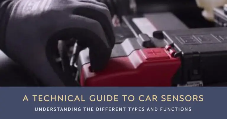
The lead-acid battery provides power to start the engine and run accessories. It is maintained by the charging system while driving. It supplies high amperage to the starter motor when starting the engine.
Batteries are rated by CCA (cold cranking amps) which indicates the sustained output it can deliver at 0°F. Higher CCA batteries provide more starting power. Reserve capacity indicates how long it can run accessories without the alternator.
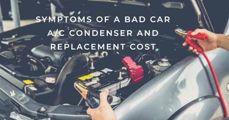
Battery condition should be checked regularly. Corroded or loose terminals can cause starting issues. A load tester or multimeter can check the state of charge. Dead cells will indicate the need for replacement.
Alternator
The alternator charges the battery and powers the electrical system while the engine is running. Belt driven off the engine, its internal components include:
- Rotor – spinning part that generates alternating current.
- Stator – stationary winding coils that output AC voltage.
- Diodes – rectifiers that convert AC to DC to charge the battery.
- Voltage regulator – controls voltage output.
Typical output is 130-200 amps. The drive belt must be in good condition to prevent slipping and maintain proper charging. Faulty alternators will fail to keep the battery charged.
Wiring, Terminals and Connectors
Insulated wiring transmits power and signals between components. Proper gauge wires matched to the load are required to carry current without overheating. Tracing color coded wiring diagrams is needed for diagnosing problems.
Terminals, connectors and splices must make solid contact to avoid resistance and voltage drops. Their quality and fitment are extremely important for reliable electrical function. Exposed copper or corroded terminals cause issues.
Fuses and Circuit Breakers
Fuses and circuit breakers protect wiring from excessive current flow. If a component shorts internally or a wire shorts to ground, the fuse blows to break the circuit. This prevents damage such as fires. Each circuit has a fuse rated for its expected normal load. Never install higher capacity fuses during troubleshooting.
Relays and Solenoids
Relays are electrically controlled switches that allow a low current circuit to control a higher powered circuit. When energized by the coil, their internal contacts close to complete the higher amperage circuit. Applications include headlights, electric cooling fans, fuel pumps, etc.
Solenoids also operate as a controlled electrical-mechanical switch. When energized they move a plunger which actuates the component. Starter and transmission solenoids are common examples. Faulty relay or solenoid contacts cause intermittent operation.
Control Modules and Computers
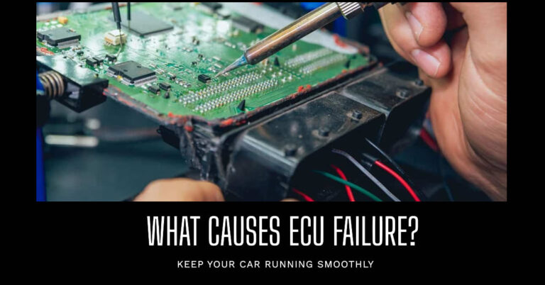
also called ECUs (Engine Control Unit) or PCM (Powertrain Control Module). These receive sensor inputs, run control logic programs, and send signals to actuators to manage engine and transmission operation. The main modules are:
- Engine computer – Controls fuel injection, ignition timing, emissions controls.
- Transmission computer – Shift timing, torque converter lockup, etc.
- ABS module – Antilock brake modulation
- Body Control Module – Accessories, power windows, etc.
Problems in input or output circuits can cause all sorts of drivability, performance, or operation issues. Diagnostics may require a professional scan tool. Programming updates may be needed.
Electrical Power Distribution
High current feed wires distribute power from the battery to major branch circuits:
- Fusible links – Heavy gauge wires that act as fuses to protect main circuits.
- Junction block – Main distribution point to bussed fuses for each branch circuit.
- Terminal blocks and splice points – Intermediate connection points.
- Switch panels – Contains switches, gauges, indicator lights.
- Individual devices and components.
Proper wire gauge and insulation is critical to avoid overheating and shorts. Circuits must be traceable through wiring diagrams during troubleshooting.
Grounding the Electrical System
Ground completes the circuit by providing the return path for electrons back to the negative side of the battery. Reliable grounding is vital for proper electrical function.
Major ground points are the engine block, chassis, and body which are bonded together by ground straps. Separate ground points help minimize noise in sensitive circuits. Exposed metal areas under the hood may also serve as ground connection points.
Corrosion on ground points causes resistance which leads to electrical gremlins. Loose ground wires are another common issue.
Ignition Switch and Lock Cylinder
The ignition switch controls electrical power from the battery. It contains several contact positions activated by the lock cylinder.
Typical switch positions are:
- OFF/LOCK – No power to any circuits, key can be removed.
- ACC – Accessory position, radio works.
- ON/RUN – Powers ignition, instruments, control modules.
- START – Engages starter motor to crank engine. Spring returns to RUN position when released.
Failure causes an inability to activate starter, run accessories or circuits. Switch contacts may need cleaning. Lock cylinders wear out over time.
Voltage Drops
Any resistance or loose connections in the circuit causes a slight voltage drop. Some voltage drop is normal. Excessive drop can cause problems. Major causes:
- Poor ground connections – Corrosion increases resistance.
- Undersized wiring – Too small of gauge for load.
- Loose, damaged or corroded connections – Introduce extra resistance.
- Faulty components – Damaged internals increase resistance.
Measuring voltage right at components isolates abnormal drops. 0.5V drop is typical, 1V or more indicates a problem.
Key Automotive Circuits
- Starter – Battery, ignition switch, starter solenoid and motor. Very high current.
- Charging – Alternator, battery, fusible link, voltage regulator. High current.
- Ignition – Coil packs, spark plugs, distributor, ignition module. Up to 40kV.
- Fuel – Pump, filter, injectors or carburetor, pressure regulator.
- Engine Management – Sensors, ECU, actuators to control ignition, fueling, emissions. Data links to other modules.
- Lighting – Headlights, brake lights, turn signals. High wattage bulbs. Relays control high beams, actuation.
- Accessories – Circuits for radio, power windows, seats, windshield wipers, gauges, cruise control.
- Charging – Alternator, regulator, battery, fusible links, ammeter, warning light. High current.
Proper troubleshooting isolates problems to one of these systems based on what fails to work properly.
Common Electrical System Issues
Some typical electrical problems are:
- Battery dies or cranks weakly – Faulty charging system, bad battery.
- Lights dim or flicker – Loose ground or alternator belt. Bad connection.
- No crank, no start – Dead battery, bad starter, ignition switch issue.
- Intermittent stalling – Ignition coil/module issue, crank/cam sensor failure.
- Electrical gremlins – Corroded ground, wiring damage, ECU problem.
- Fuse blowing – Short circuit or overload in that circuit.
- Gas gauge, speedometer malfunction – Bad ground or sender unit. Open in wiring.
- Power window or seat failure – Burnt switch, motor issue, wiring open/short.
- Hyperflashing indicators – Faulty turn signal flasher unit.
Many come down to loose, corroded or damaged wiring and connections.
Diagnostic Steps for Electrical Issues
Systematically narrow down and isolate the cause of the problem:
- Note complaint and symptoms. When does the failure occur? Can it be reproduced?
- Inspect visually – damaged wiring, burnt/corroded connectors, loose terminals?
- Check fuses and relays – Any blown fuses? Swap the relay with a known good one.
- Measure voltage and ground at component with multimeter. Is power getting to the device? Clean ground?
- Refer to wiring diagram. Trace circuits end-to-end. Confirm power and ground at each step.
- Wiggle/shake wiring while monitoring voltage. Dropouts indicate broken conductor inside insulation.
- Check for trouble codes with an OBD2 scanner. May reveal failures in computer controlled systems.
- Use deduction to divide systems. Isolate problem to one circuit based on what works/doesn’t work.
- Repair wiring failures with proper splice connectors. Replace damaged components.
- Verify operation restored by testing. Make sure issue is fully resolved.
Preventing Electrical System Issues
Proper maintenance goes a long way in preventing problems, such as:
- Regularly clean and tighten battery connections. Check for corrosion.
- Inspect wiring condition. Look for damaged insulation, exposed copper. Repair or replace.
- Ensure alternator belt is in good shape. Replace if cracked or glazed.
- Check all fuses and replace any that are burnt out. Use the correct rating.
- Clean any corroded or oxidized ground and power connections.
- Fix minor wiring issues immediately before they lead to bigger problems.
- Avoid excessive electrical accessories that can overload circuits.
- After water exposure, thoroughly dry all connections to prevent corrosion.
- Check battery condition and charge periodically. Load test or replace as needed.
Safety Tips for Working on Electrical Systems
- Wear insulating gloves and be cautious when working near the battery. Avoid shorting terminals.
- Never disconnect the battery while the engine is running, or you may damage computer components.
- Don’t wear jewelry which could contact hot terminals or battery posts accidentally.
- Disconnect negative terminal first and reconnect it last to avoid short circuits while working.
- Avoid contact with exhaust or extremely hot engine parts which could also ground you.
- Be careful not to damage insulation on wiring. Exposed conductors increase fire risk.
- Take care not to short wiring to the chassis or other components while probing circuits.
- Make sure nothing drops onto the battery which could spark or short the terminals.
Conclusion
Automotive electrical systems provide the foundation for reliable operation of the vast electronics in modern vehicles. Understanding how electricity flows through the intricate circuitry allows diagnosis of problems through logical troubleshooting. With maintenance and repair of components and wiring, the system can be kept in optimal condition to handle the demands of starting, charging, and powering accessories. Mastering electrical principles, diagnostic techniques and safe working practices gives you the expertise to handle any electrical issue quickly and correctly.

