2 & 3 Wire Crank Sensor Wiring Diagram: A Comprehensive Guide

The crank sensor is an integral part of a car’s engine management system. This tiny sensor plays a crucial role in ensuring the engine runs smoothly.
But what exactly are the differences between 2 and 3 wire crank sensors? How are they wired differently? And what do their wiring diagrams look like?
In short, 2 wire crank sensors operate using the signal and ground wires, while 3 wire sensors also have a power wire. We’ll dive into the specifics of how each one functions and detail the wiring in diagrams below.
This post will outline everything you need to know about 2 and 3 wire crank sensor wiring diagrams. We’ll cover:
- The differences between 2 and 3 wire configurations
- How each sensor works
- Wiring diagrams for both systems
- Troubleshooting crank sensor issues
- Step-by-step crank sensor replacement
- Answers to frequently asked questions
Let’s start by understanding exactly what crank sensors do.
Table of Contents
What is a Crank Sensor?
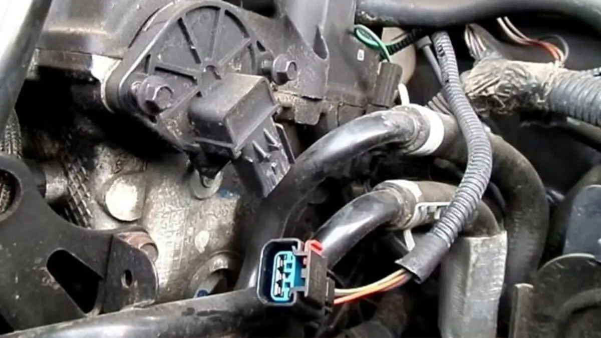
The crank sensor monitors the position and rotational speed of the crankshaft. This information is used by the car’s computer to calculate ignition timing and fuel injection timing.
The sensor works by reading a toothed wheel on the crankshaft. As the wheel spins, the teeth pass the sensor and generate a magnetic field. This creates an AC signal that is sent to the computer.
By constantly monitoring the crankshaft, the sensor allows the computer to determine:
- Engine speed (RPM)
- Whether the engine is running
- Crankshaft position relative to pistons
- If misfires are occurring
This input is vital for controlling ignition, fuel injection, and engine performance. A faulty crank sensor can cause issues like:
- Difficult starting or stalling
- Rough idle
- Reduced power and acceleration
- Misfiring and backfiring
Now let’s look at the differences between 2 and 3 wire configurations.
Difference Between 2 and 3 Wire Crank Sensors
2 wire crank sensors have the following connections:
- Signal wire – Sends the generated AC signal to the car computer
- Ground wire – Provides a ground reference for the signal
3 wire crank sensors include an additional wire:
- Power wire – Supplies 5-12V power to the sensor
- Signal wire
- Ground wire
In essence, 3 wire sensors receive an external power source to operate, while 2 wire models generate their own power internally from the spinning crankshaft.
2 wire sensors are simpler and cheaper, but 3 wire configurations allow for stronger and more stable signals. Many modern engines use 3 wire sensors for added reliability.
Next let’s look at how each one operates.
How a 2 Wire Crank Sensor Works?
Here is a simple 2 wire crank sensor diagram:
Without an external power source, 2 wire crank sensors generate their own voltage from the movement of the crankshaft.
As the toothed reluctor wheel spins, the passing metal teeth induce a magnetic field in the sensor coil windings. This magnetic flux change generates a small AC voltage, usually around 0.2V to 1V.
This AC signal is sent on the sensor’s signal wire to the engine computer. The computer uses it to monitor crank position and calculate engine timing.
The sensor needs a ground reference, so the second wire connects to chassis ground. This completes the simple circuit.
Advantages of 2 wire crank sensors:
- Simple and inexpensive
- Less wiring needed
Disadvantages:
- Prone to noise and interference in signal
- Lower voltage output than powered sensors
- Can be influenced by rust and dirt on crankshaft reluctor ring
Now let’s look at how 3 wire crank sensors improve performance.
How a 3 Wire Crank Sensor Works?
As you can see, 3 wire sensors add a power feed wire to the circuit. This provides constant voltage, usually between 5-12V, from the car’s electrical system.
Having steady external power allows the sensor to produce a much stronger and more stable AC signal, in the range of 0.5V to over 100V. This improves accuracy.
The powered signal wire delivers the crankshaft position data to the ECU. The sensor grounds through the third wire.
Benefits of 3 wire crank sensors:
- Stronger and more precise signals
- Less prone to interference and environmental factors
- More accurate measurement of crank position
Now let’s look at complete wiring diagrams.
2 Wire Crank Sensor Wiring Diagram
Check out how simple the 2 wire sensor system is:
- The sensor connects directly to the car’s computer (ECU) via the signal wire
- The ground wire completes the circuit by attaching to the engine block ground
Since the sensor generates its own voltage, no external power source is needed.
The computer monitors the sensor signal for RPM, crank position, misfires, and timing information to control the engine.
This basic diagram applies to most 2 wire crank configurations. Next let’s look at 3 wire systems.
3 Wire Crank Sensor Wiring Diagram
The extra wire in 3 wire sensors is the power feed from the car’s electrical system, usually the ignition switch:
- The power wire provides 5-12V to the sensor.
- The signal wire carries the crank position data to the ECU.
- The ground wire completes the circuit.
With the constant external power, the 3 wire sensor can produce strong, accurate signals for the computer to read.
This diagram shows the standard wiring, but variations exist between car models. Consult a vehicle-specific diagram to be sure.
Next let’s go over some troubleshooting tips for crank sensors.
Troubleshooting Crank Sensor Issues
Here are common symptoms of a failing crank sensor:
- Difficulty starting or stalling
- Stumbling acceleration
- Fluctuating RPM
- Rough idle
- Check Engine Light
- Misfiring and backfiring
Here are steps to diagnose crank sensor problems:
- Visual inspection – Check for damage to wiring harness, loose or corroded connections
- Resistance test – Check that resistance values match spec
- Graph live data – Monitor sensor waveform on scan tool, check for drop outs
- Run “crank relearn” procedure – This resets ECU crank memory if sensor was replaced
- Still having issues? – May be problem with reluctor ring, ECU, or other components
Replacing the sensor may be needed if it’s intermittently cutting out or producing too low/high voltage.
Crank Sensor Replacement
Here are the key steps to replace a crank position sensor:
Safety First
- Allow engine to fully cool before attempting replacement. The sensor can be hot!
Gather Tools
- Socket set with extensions
- Pliers
- Multimeter
- Anti-seize compound
- Clean shop rags
Locate the Sensor
- Consult vehicle diagrams to find sensor location around crankshaft pulley
- Not always easy to reach! Be prepared to work in tight spots.
Disconnect Power
- Unplug sensor electrical connector.
- Unbolt sensor carefully using proper size socket. Don’t drop or lose bolts!
Remove Old Sensor
- Twist and wiggle sensor to free it from mounting hole. Take care not to damage threads.
- Confirm old part number matches new replacement.
Install New Sensor
- Use anti-seize on sensor threads to prevent seizing.
- Tighten new sensor to torque spec with socket. Don’t overtighten!
Reconnect
- Plug in electrical connector. Make sure it clicks and latches.
- Secure any loose wiring with zip ties or clamps.
Reset ECU
- Perform “crankshaft position relearn” procedure to set sensor alignment.
Be patient, reinstalling the sensor properly is key to resolving issues. Now let’s answer some common questions.
FAQ
What happens if crank sensor fails?
The engine computer won’t receive vital timing data, causing driveability problems like misfires and stalling. The check engine light usually illuminates if sensor stops functioning.
Why does my car die randomly?
An intermittent crank sensor signal dropout can cause the engine to randomly stall or shut off. These dropouts resemble loss of power or fuel delivery. Test sensor signal with a graphing multimeter.
Can a bad crank sensor cause no start?
Yes, a dead crank sensor can prevent fuel injection and ignition spark, preventing engine from starting. Confirm sensor has proper resistance and isn’t grounding out before replacing.
Conclusion
Understanding crank sensor wiring and operation is vital for diagnosing engine issues. Key points:
- 2 wire sensors generate internal voltage from crankshaft movement
- 3 wire sensors use an external power feed for stronger signals
- Sensor failure causes hard starting, stalling, rough running
- Inspect wiring, perform resistance tests, and check waveforms when troubleshooting
- Follow proper procedure when replacing faulty sensors
Hopefully this outlines everything you need to know about 2 and 3 wire crank sensor wiring diagrams. Here are some final helpful charts:
2 vs 3 Wire Crank Sensor Comparison
| 2 Wire | 3 Wire | |
|---|---|---|
| Wires | Signal, Ground | Power, Signal, Ground |
| Voltage Source | Internal – from crankshaft | External power feed |
| Output Signal Strength | Low – 0.2V to 1V | Higher – 0.5V to over 100V |
| Complexity | Simple | More complex |
| Cost | Lower | Higher |
Pros and Cons of Each Type
2 Wire Sensor
Pros:
- Simple and inexpensive
- Less wiring complexity
Cons:
- More prone to signal interference
- Lower voltage output
3 Wire Sensor
Pros:
- Power wire provides stable voltage
- Produces stronger signal
- More accurate reading of crank position
Cons:
- More expensive
- Extra wiring needed


![Resonator Delete vs. Muffler Delete [Guide] ? Resonator Delete vs. Muffler Delete [Guide] ?](https://automadesimply.com/wp-content/uploads/2023/08/resonator-delete-vs.-muffler-delete-768x432.jpg)


